Textbook Question
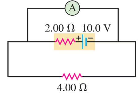
The circuit shown in Fig. E contains two batteries, each with an emf and an internal resistance, and two resistors. Find the current in the circuit (magnitude and direction).
1590
views

 Verified step by step guidance
 03:07
03:07 05:55
05:55 07:14
07:14The circuit shown in Fig. E contains two batteries, each with an emf and an internal resistance, and two resistors. Find the current in the circuit (magnitude and direction).
A copper transmission cable km long and cm in diameter carries a current of A. How much electrical energy is dissipated as thermal energy every hour?
The circuit shown in Fig. E contains two batteries, each with an emf and an internal resistance, and two resistors. Find the terminal voltage of the -V battery.
An idealized ammeter is connected to a battery as shown in Fig. E. Find the reading of the ammeter.
The circuit shown in Fig. E contains two batteries, each with an emf and an internal resistance, and two resistors. Find the potential difference of point with respect to point .
An idealized ammeter is connected to a battery as shown in Fig. E. Find the current through the - resistor.