
Textbook Question
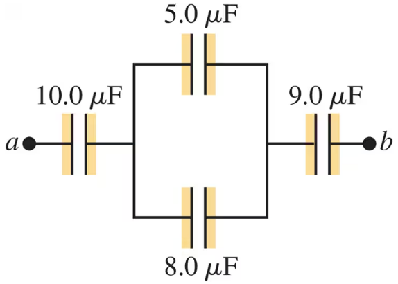
For the system of capacitors shown in Fig. E, find the equivalent capacitance between and .
2719
views
1
rank

 Verified step by step guidance
 08:02
08:02
 09:51
09:51 04:03
04:03For the system of capacitors shown in Fig. E, find the equivalent capacitance between and .
In Fig. E, F, F, and F. The capacitor network is connected to an applied potential .
(a) After the charges on the capacitors have reached their final values, the charge on is mC. What are the charges on capacitors and ?
(b) What is the applied voltage ?
A -F, parallel-plate, air capacitor has a plate separation of mm and is charged to a potential difference of V. Calculate the energy density in the region between the plates, in units of J/m3.
A capacitor is made from two hollow, coaxial, iron cylinders, one inside the other. The inner cylinder is negatively charged and the outer is positively charged; the magnitude of the charge on each is pC. The inner cylinder has radius mm, the outer one has radius mm, and the length of each cylinder is cm.
(a) What is the capacitance?
(b) What applied potential difference is necessary to produce these charges on the cylinders?
Figure E shows a system of four capacitors, where the potential difference across ab is V. How much charge is stored by this combination of capacitors?
A spherical capacitor contains a charge of nC when connected to a potential difference of V. If its plates are separated by vacuum and the inner radius of the outer shell is cm, calculate: (a) the capacitance; (b) the radius of the inner sphere; (c) the electric field just outside the surface of the inner sphere.