
Ch 29: Electromagnetic Induction
Young & Freedman Calc - University Physics 14th Edition
Young & Freedman Calc14th EditionUniversity PhysicsISBN: 9780321973610Not the one you use?Change textbook
Chapter 29, Problem 40e

The magnetic field B at all points within the colored circle shown in Fig. E29.15 has an initial magnitude of 0.750 T. (The circle could represent approximately the space inside a long, thin solenoid.) The magnetic field is directed into the plane of the diagram and is decreasing at the rate of -0.0350 T/s. If the ring is cut at some point and the ends are separated slightly, what will be the emf between the ends?
<Image>

Verified step by step guidance
1
Understand that the problem involves electromagnetic induction, specifically Faraday's law of induction, which states that a changing magnetic field within a loop induces an electromotive force (emf) in the loop.
Identify that the magnetic field is decreasing at a rate of -0.0350 T/s. This rate of change of the magnetic field is crucial for calculating the induced emf.
Use Faraday's law of induction, which is given by the formula: ε=-dΦ/dt, where ε is the induced emf and Φ is the magnetic flux.
Calculate the magnetic flux Φ using the formula: Φ=BA, where B is the magnetic field and A is the area of the circle. Since the magnetic field is uniform, the flux is simply the product of the field and the area.
Substitute the rate of change of the magnetic field into Faraday's law to find the induced emf: ε=-A(-0.0350). The negative sign in Faraday's law indicates the direction of the induced emf, but since the field is decreasing, the induced emf will be positive.

Verified video answer for a similar problem:

This video solution was recommended by our tutors as helpful for the problem above.
Video duration:
7m
Was this helpful?

Key Concepts

Here are the essential concepts you must grasp in order to answer the question correctly.

Faraday's Law of Electromagnetic Induction

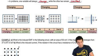
Faraday's Law states that a change in magnetic flux through a circuit induces an electromotive force (emf) in the circuit. The induced emf is proportional to the rate of change of the magnetic flux. In this scenario, the decreasing magnetic field within the circle causes a change in magnetic flux, which induces an emf in the ring.
Recommended video:
Guided course
09:26
Faraday's Law

Magnetic Flux

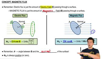
Magnetic flux is a measure of the quantity of magnetism, considering the strength and extent of a magnetic field. It is calculated as the product of the magnetic field (B) and the area (A) it penetrates, perpendicular to the field. In this problem, the change in magnetic flux due to the decreasing magnetic field is crucial for determining the induced emf.
Recommended video:
Guided course
04:52
Magnetic Flux

Lenz's Law

Lenz's Law states that the direction of the induced emf and current will be such that it opposes the change in magnetic flux that produced it. This principle helps determine the polarity of the induced emf in the ring when the magnetic field decreases. It ensures that the induced current creates a magnetic field opposing the reduction in the original field.
Recommended video:
Related Practice
Textbook Question

The magnetic field B at all points within the colored circle shown in Fig. E29.15 has an initial magnitude of 0.750 T. (The circle could represent approximately the space inside a long, thin solenoid.) The magnetic field is directed into the plane of the diagram and is decreasing at the rate of -0.0350 T/s. What is the emf between points a and b on the ring?

<Image>

1967
views
Textbook Question

The magnetic field B at all points within the colored circle shown in Fig. E29.15 has an initial magnitude of 0.750 T. (The circle could represent approximately the space inside a long, thin solenoid.) The magnetic field is directed into the plane of the diagram and is decreasing at the rate of -0.0350 T/s. What is the current in the ring if its resistance is 4.00 Ω?

<Image>

1427
views
Textbook Question

A parallel-plate, air-filled capacitor is being charged as in Fig. 29.23. The circular plates have radius 4.00 cm, and at a particular instant the conduction current in the wires is 0.520 A. What is the rate at which the electric field between the plates is changing?

292
views
Textbook Question

A long, straight solenoid with a cross-sectional area of 8.00 cm2 is wound with 90 turns of wire per centimeter, and the windings carry a current of 0.350 A. A second winding of 12 turns encircles the solenoid at its center. The current in the solenoid is turned off such that the magnetic field of the solenoid becomes zero in 0.0400 s. What is the average induced emf in the second winding?

3153
views
1
rank
Textbook Question

A parallel-plate, air-filled capacitor is being charged as in Fig. 29.23. The circular plates have radius 4.00 cm, and at a particular instant the conduction current in the wires is 0.520 A. (a) What is the displacement current density jD in the air space between the plates?

313
views
Textbook Question

The magnetic field B at all points within the colored circle shown in Fig. E29.15 has an initial magnitude of 0.750 T. (The circle could represent approximately the space inside a long, thin solenoid.) The magnetic field is directed into the plane of the diagram and is decreasing at the rate of -0.0350 T/s. What is the shape of the field lines of the induced electric field shown in Fig. E29.15 , within the colored circle?

<Image>

1784
views