Textbook Question
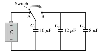
What are the charge on and the potential difference across each capacitor in FIGURE P26.57?
317
views

 Verified step by step guidance
 08:02
08:02 04:08
04:08 09:57
09:57What are the charge on and the potential difference across each capacitor in FIGURE P26.57?
Six identical capacitors with capacitance C are connected as shown in FIGURE P26.59. What is the potential difference between points a and b?
Two 2.0 cm×2.0 cm metal electrodes are spaced 1.0 mm apart and connected by wires to the terminals of a 9.0 V battery. What are the charge on each electrode and the potential difference between them?
An isolated 5.0 μF parallel-plate capacitor has 4.0 mC of charge. An external force changes the distance between the electrodes until the capacitance is 2.0 μF. How much work is done by the external force?
Capacitors C₁ = 10 μF and C₂ = 20 μF are each charged to 10 V, then disconnected from the battery without changing the charge on the capacitor plates. The two capacitors are then connected in parallel, with the positive plate of C₁ connected to the negative plate of C₂ and vice versa. Afterward, what are the charge on and the potential difference across each capacitor?
You've built a device that uses the energy from a rapidly discharged capacitor to launch the capacitor straight up. One capacitor, with a mass of 3.5 g, is launched to a height of 1.6 m after having been charged to 100 V. What is its capacitance in μF?