26. Capacitors & Dielectrics
Solving Capacitor Circuits
Learn with other creators
Practice this topic
- Multiple Choice
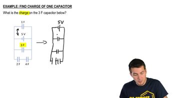
What is charge and voltage across each capacitor below?
2054views25rank3comments - Multiple Choice
What is the voltage of the battery below?
1258views17rank6comments - Multiple Choice
What is the charge on the 5 F capacitor? (hint:be careful with series vs parallel)
1287views24rank2comments - Textbook Question
What are the charge on and the potential difference across each capacitor in FIGURE P26.57?
180views - Textbook Question
Six identical capacitors with capacitance C are connected as shown in FIGURE P26.59. What is the potential difference between points a and b?
133views - Textbook Question
Initially, the switch in FIGURE P26.61 is in position A and capacitors C₂ and C₃ are uncharged. Then the switch is flipped to position B. Afterward, the voltage across C₁ is 4.0 V. What is the emf of the battery?
790views - Textbook Question
Capacitors C₁ = 10 μF and C₂ = 20 μF are each charged to 10 V, then disconnected from the battery without changing the charge on the capacitor plates. The two capacitors are then connected in parallel, with the positive plate of C₁ connected to the negative plate of C₂ and vice versa. Afterward, what are the charge on and the potential difference across each capacitor?
115views - Multiple ChoiceConsider a capacitor circuit where a battery is connected. Just after the circuit is completed, at what rate is the battery supplying electrical energy to the circuit?411views


