Here are the essential concepts you must grasp in order to answer the question correctly.
Impedance in RLC Circuits
In an L-R-C series circuit, the total impedance (Z) is a combination of the resistance (R), inductive reactance (XL), and capacitive reactance (XC). Impedance determines how much current flows in the circuit when a voltage is applied. It is calculated using the formula Z = √(R² + (XL - XC)²), where XL = 2πfL and XC = 1/(2πfC). Understanding impedance is crucial for analyzing the circuit's behavior under alternating current (AC).
Recommended video:
Power in AC Circuits
The power supplied by an AC generator in an RLC circuit can be calculated using the formula P = VIcos(φ), where V is the rms voltage, I is the rms current, and φ is the phase angle between the voltage and current. The phase angle is determined by the impedance and the resistance in the circuit. This concept is essential for determining both the total power supplied and the power dissipated in the resistor.
Recommended video:
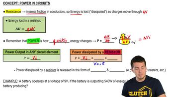
Resistive Power Dissipation
The power dissipated in the resistor (P_R) in an RLC circuit is given by P_R = I²R, where I is the rms current through the resistor. This power represents the energy converted to heat due to the resistance in the circuit. Understanding this concept is important for evaluating how much energy is lost in the resistor compared to the total power supplied by the generator.
Recommended video:


 08:40
08:40