Everyone, in earlier videos, we saw how to solve PV diagram problems. And in more recent videos, we've looked at heat engine problems. Well, some problems like the one that we're going to work out below will give you a PV diagram for a heat engine and then ask you to calculate something, like the total work done by the engines. We're going to put those ideas together in this video, and I'm going to show you how to calculate the work in heat engines by using the PV diagram. And what we're going to see is we're going to see the relationship between the PV diagram steps and the quantities that we use in our energy flow diagrams. So let's go ahead and get started. We're actually just going to jump straight into our problem because there's a lot of stuff that we already know how to do. So let's check it out. In this problem, we have 2 moles of a gas, and it's basically undergoing a cyclic process. What we're told here is that heat is removed from this gas at constant pressure from a to b. Remember, that just means that it's an isobaric process. Then from b to c, we're adding heat at constant volume. So this is isovolumetric. And then finally, the gas is going to expand isothermally. So that just means it's going to sort of ride along this curve right here, go back to a, and then the whole thing is going to repeat over again. So that's actually the first point I want to make here. Remember that heat engines are cyclic processes. They start and end at the same point at the same initial state. But what you need to know here is that on PV diagrams, they will actually always run-in clockwise loops. Notice how we've gone through a cycle like this, but the overall pattern of this loop is in the clockwise direction. Alright. So that's always going to be true for heat engines. Alright. So let's take a look at this problem here, because the first thing we want to calculate in part a is the heat transfer of each process. So we have 3 processes we want to calculate q for. So we have q from a to b, and then we have q from b to c, and then we have q from c back to a again. Alright? So we spent a lot of time developing our equations in this table here for special processes. That's the that's basically what we're going to do here. We're just going to look at each process and then figure out which equation of q that we use from this row here. So let's get started. So from a to b, we know this is an isobaric process, constant pressure. So we look th...
We have 2 moles. CP just comes from this table here. It's a monoatomic gas, so we're going to use
Finally, this last process here,
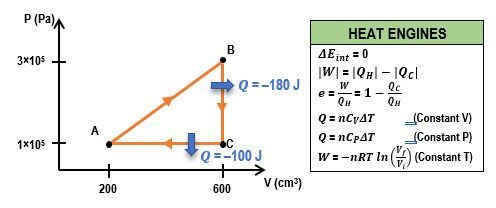
So that's going to be the work done by the engine. Now how do we do this? Well, you may remember from our video on cyclic processes that whenever you have a cycle, the work that's done is going to be the area that is enclosed within the loop. So in other words, the work done is going to be the area. So how do we do that? Well, unfortunately, there's a couple of problems here because, 1, we have this sort of curved isothermal process, so we can't use something like a triangle or anything like that. And we also don't have any of the values for pressure or volume or anything that we need to calculate the area. So while the work done by the engine is actually the area that's in this shape, we just can't calculate it. So we're going to have to use a different equation. Now in more recent videos, remember, we've talked a lot about heat engines, and we've been using these energy flow diagrams. And remember, for heat engines, the work done is just equal to
Now we do the same exact thing for the