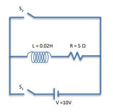
In an LR circuit, which consists of an inductor (L) and a resistor (R), the behavior of current can be categorized into two main processes: current growth and current decay. When a switch (S1) is closed while another switch (S2) remains open, a continuous loop is formed, allowing current to flow from the battery through the inductor and resistor. This phase is characterized by current growth, where the current starts at zero and gradually increases towards its maximum value, determined by Ohm's Law as I_{max} = \frac{V}{R}, where V is the voltage of the battery.
The inductor opposes rapid changes in current due to its property of self-induction, which generates an electromotive force (EMF) that resists the increase in current. The relationship governing this behavior is described by the exponential function I(t) = I_{max} \left(1 - e^{-\frac{t}{\tau}}\right), where \tau = \frac{L}{R} is the time constant of the circuit. As time progresses, the current approaches its maximum value, and after a long time, the exponential term diminishes, indicating that the current stabilizes.
Once the battery is disconnected by opening switch S1 and closing switch S2, the circuit enters the current decay phase. In this scenario, the inductor still resists changes in current, but now the current begins to decrease as it is dissipated through the resistor. The governing equation for this decay is I(t) = I_{max} e^{-\frac{t}{\tau}}. As time increases, the current asymptotically approaches zero, indicating that the energy stored in the inductor is being released through the resistor.
The time constant \tau plays a crucial role in determining the rate of both growth and decay. A smaller time constant, resulting from a lower inductance or higher resistance, leads to faster changes in current, while a larger time constant indicates slower changes. Understanding these principles is essential for analyzing the behavior of LR circuits in various applications.


