In thermodynamics, understanding the relationship between pressure (P), volume (V), and heat transfer is crucial, especially when analyzing heat engines. A heat engine operates through a cyclic process, which means it returns to its initial state after completing a series of steps. This cycle can be represented on a PV diagram, where the area enclosed by the cycle corresponds to the work done by the engine.
In a typical heat engine cycle, there are distinct processes: isobaric (constant pressure), isovolumetric (constant volume), and isothermal (constant temperature). For example, consider a system with 2 moles of a monoatomic gas undergoing a cyclic process. The steps include:
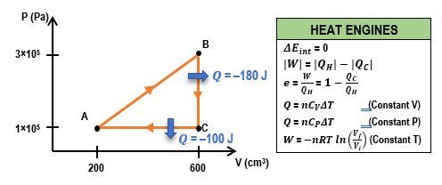
- Isobaric Process (A to B): Heat is removed from the gas at constant pressure. The heat transfer (q) can be calculated using the formula: q = nC_P \Delta T, where n is the number of moles, C_P is the molar specific heat at constant pressure, and ΔT is the change in temperature. For a monoatomic gas, C_P is given by \(C_P = \frac{5}{2}R\), where R is the ideal gas constant (approximately 8.314 J/(mol·K)). If the temperature changes from 200 K to 100 K, the heat transfer results in a negative value, indicating heat removal.
- Isovolumetric Process (B to C): Heat is added at constant volume. The heat transfer can be calculated using the formula: q = nC_V \Delta T, where C_V is the molar specific heat at constant volume, which for a monoatomic gas is \(C_V = \frac{3}{2}R\). If the temperature changes from 100 K to 200 K, this process results in a positive heat transfer value.
- Isothermal Process (C to A): The gas expands isothermally, meaning the temperature remains constant. In this case, the heat transfer is equal to the work done by the gas, which can be directly provided or calculated based on the system's parameters.
To find the total work done by the heat engine, one can use the relationship between heat transfer and work. The work done by the engine is given by the difference between the heat added from the hot reservoir and the heat removed to the cold reservoir:
W = Q_H - Q_CHere, Q_H is the total heat added during the cycle, which is the sum of the positive heat transfers, and Q_C is the absolute value of the heat removed. It is important to ensure that the signs are correctly interpreted, as heat removed is considered negative in calculations. The final work done by the engine can be calculated by substituting the values obtained from the heat transfer calculations.
In summary, analyzing a heat engine's performance involves understanding the cyclic processes represented on a PV diagram, calculating heat transfers for each process, and using these values to determine the work done by the engine. This approach not only reinforces the principles of thermodynamics but also highlights the practical applications of these concepts in real-world systems.