The magnetic field generated by current-carrying loops and solenoids is a fundamental concept in electromagnetism. When a straight wire carries a current \( I \), it produces a magnetic field \( B \) at a distance \( r \) from the wire, described by the equation:
\[ B = \frac{\mu_0 I}{2 \pi r} \]
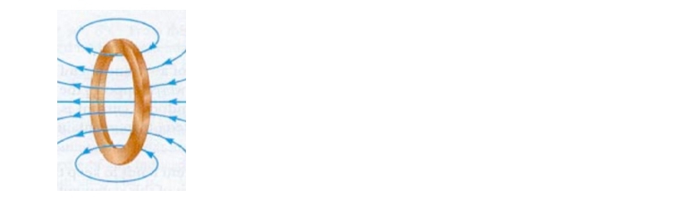
where \( \mu_0 \) is the permeability of free space. However, when the wire is formed into loops, the behavior of the magnetic field changes significantly. In a loop, the right-hand rule is applied differently: the fingers represent the direction of the current, while the thumb indicates the direction of the magnetic field. For a single loop with a counterclockwise current, the magnetic field at the center points out of the page, while for a clockwise current, it points into the page.
The magnitude of the magnetic field at the center of a loop is given by:
\[ B = \frac{\mu_0 n I}{2 R} \]
where \( n \) is the number of loops and \( R \) is the radius of the loop. It is crucial to note that \( R \) refers to the radius of the loop, while \( r \) is used for distance from a straight wire. The absence of \( \pi \) in this equation is intentional and should not be mistaken for a typographical error.
When multiple loops are present, the magnetic field strength increases proportionally with the number of loops. For example, if one loop produces a magnetic field strength of \( 10 \, \text{T} \), three loops would produce \( 30 \, \text{T} \). This principle is often utilized in electrical devices that require stronger magnetic fields.
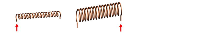
For long solenoids, the magnetic field can be described by a different equation:
\[ B = \mu_0 n I \]
where \( n \) is the number of loops per unit length. This equation highlights how the density of loops affects the strength of the magnetic field. The direction of the magnetic field in a solenoid can also be determined using the right-hand rule, where the fingers curl in the direction of the current and the thumb points in the direction of the magnetic field.
To calculate the total length of wire used in multiple loops, the formula is:
\[ \text{Total Length} = 2 \pi R n \]
where \( R \) is the radius of the loops and \( n \) is the number of loops. This relationship is essential for understanding the physical dimensions of the wire used in constructing the loops.
In practical applications, solenoids behave similarly to magnets, with distinct north and south poles, and the magnetic field lines emanate from the north pole to the south pole, resembling the field of a bar magnet.
For example, consider a wire twisted into five loops with a radius of 4 meters, carrying a 3 amp current in a counterclockwise direction. The magnetic field at the center can be calculated using the previously mentioned formula, yielding a specific magnitude and direction of the magnetic field, which can be determined using the right-hand rule.
Understanding these principles is crucial for applications in electromagnetism, including electric motors, transformers, and inductors, where the manipulation of magnetic fields is essential for functionality.