
Measurements made on circuits that contain large resistances can be confusing. Consider a circuit powered by a battery ε = 15.000 V with a 10.00-MΩ resistor in series with an unknown resistor R. As shown in Fig. 26–92, a particular voltmeter reads V1 = 366 mV when connected across the 10.00 -MΩ resistor and this meter reads V2 = 7.317 V when connected across R. Determine the value of R. [Hint: Define RV as the voltmeter’s internal resistance.]
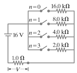
The circuit shown in Fig. 26–89 is a primitive 4-bit digital-to-analog converter (DAC). In this circuit, to represent each digit (2n) of a binary number, a “1” has the nᵗʰ switch closed whereas zero (“0”) has the switch open. For example, 0010 is represented by closing switch n = 1, while all other switches are open. Show that the voltage V across the 1.0 - Ω resistor for the binary numbers 0001, 0010, 0100, and 1010 (which represent 1, 2, 4, 10) follows the pattern that you expect for a 4-bit DAC.

Verified step by step guidance
Verified video answer for a similar problem:
Key Concepts
Digital-to-Analog Conversion
Binary Number Representation
Voltage Division in Circuits
Consider two unequal resistors, of resistance R1 and R2, that are connected either in series or in parallel. Fill in the Table below assuming the electric potential on the low-voltage end of the combination is VA volts and the potential at the high-voltage end of the combination is VB volts. First draw diagrams.
A galvanometer has an internal resistance of 32 Ω and deflects full scale for a 48-μA current. Describe how to use this galvanometer to make a voltmeter to give a full scale deflection of 250 V.
In the circuit shown in Fig. 26–75, the 33-Ω resistor dissipates 0.80 W. What is the battery voltage?
The performance of the starter circuit in a car can be significantly degraded by a small amount of corrosion on a battery terminal. Figure 26–88a depicts a properly functioning circuit with a battery (12.5-V emf, 0.02-Ω internal resistance) attached via corrosion-free cables to a starter motor of resistance Rs = 0.15Ω. Sometime later, corrosion between a battery terminal and a starter cable introduces an extra series resistance of only RC = 0.10Ω into the circuit as suggested in Fig. 26–88b. Let P0 be the power delivered to the starter in the circuit free of corrosion, and let P be the power delivered to the starter with corrosion. Determine the ratio P/P0.
