At a given instant, a 2.4-A current flows in the wires connected to a parallel-plate capacitor. What is the rate at which the electric field is changing between the plates if the square plates are 1.60 cm on a side?
Ch. 30 - Inductance, Electromagnetic Oscillations, and AC Circuits
Giancoli Douglas5th editionPhysics for Scientists and EngineersISBN: 9780137488179Not the one you use?Change textbook
All textbooks
Giancoli Douglas 5th edition
Ch. 30 - Inductance, Electromagnetic Oscillations, and AC Circuits
Problem 4
Giancoli Douglas 5th edition
Ch. 30 - Inductance, Electromagnetic Oscillations, and AC Circuits
Problem 4Chapter 29, Problem 4
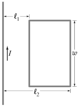
(III) A long straight wire and a small rectangular wire loop lie in the same plane, Fig. 30β25. Determine the mutual inductance in terms of πβ, πβ, and w. Assume the wire is very long compared to πβ, πβ, and w, and that the rest of its circuit is very far away compared to πβ, πβ, and w.

Verified step by step guidance1
Step 1: Understand the concept of mutual inductance. Mutual inductance (M) is a measure of how much magnetic flux through one circuit is linked to the current in another circuit. In this case, the magnetic field generated by the long straight wire induces a flux through the rectangular loop.
Step 2: Write the expression for the magnetic field (B) due to a long straight wire carrying current I. The magnetic field at a distance r from the wire is given by: , where ΞΌβ is the permeability of free space.
Step 3: Calculate the magnetic flux (Ξ¦) through the rectangular loop. The flux is the integral of the magnetic field over the area of the loop. For a small segment of the loop at a distance r from the wire, the flux contribution is: , where Ο is the width of the loop. Integrate this expression over the length of the loop (from rβ to rβ, where rβ and rβ are the distances of the near and far sides of the loop from the wire).
Step 4: Express the total flux through the loop. After integration, the total flux is: . Here, the natural logarithm accounts for the integration over the loop's length.
Step 5: Relate the mutual inductance (M) to the flux and current. By definition, mutual inductance is given by: . Substitute the expression for Ξ¦ from Step 4 to find M in terms of πβ, πβ, and Ο. Simplify the expression to complete the solution.

Verified video answer for a similar problem:
This video solution was recommended by our tutors as helpful for the problem above.
Video duration:
5mWas this helpful?
Key Concepts
Here are the essential concepts you must grasp in order to answer the question correctly.
Mutual Inductance
Mutual inductance is a measure of the ability of one electrical circuit to induce an electromotive force (EMF) in another nearby circuit due to a change in current. It is denoted by the symbol M and depends on the geometry of the circuits, their relative positions, and the magnetic permeability of the medium between them. The mutual inductance can be calculated using the formula M = (NβΞ¦β)/Iβ, where Nβ is the number of turns in the second circuit, Ξ¦β is the magnetic flux through the second circuit due to the first, and Iβ is the current in the first circuit.
Recommended video:
Guided course
Mutual Induction
Magnetic Flux
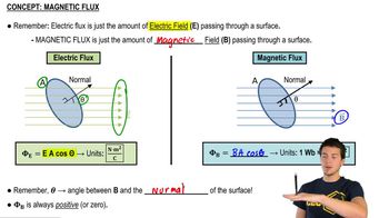
Magnetic flux refers to the total magnetic field passing through a given area and is a crucial concept in electromagnetism. It is calculated as the product of the magnetic field strength (B) and the area (A) through which the field lines pass, taking into account the angle (ΞΈ) between the field lines and the normal to the surface: Ξ¦ = BΒ·AΒ·cos(ΞΈ). In the context of mutual inductance, the magnetic flux generated by one circuit influences the induced EMF in another circuit.
Recommended video:
Guided course
Magnetic Flux
Long Wire Approximation
The long wire approximation simplifies the analysis of magnetic fields generated by a straight wire carrying current. When the wire length is significantly greater than the distances involved in the circuit (like the dimensions of the loop), the magnetic field can be considered uniform across the area of interest. This approximation allows for easier calculations of mutual inductance, as it assumes that the magnetic field lines are parallel and evenly distributed around the wire, simplifying the integration needed to find the total magnetic flux.
Recommended video:
Guided course
Lenz's Law for a Long Straight Wire
Related Practice
Textbook Question
994
views
Textbook Question
(II) If the solenoid in Fig. 29β47 is being pulled away from the loop shown, in what direction is the induced current in the loop? Explain.
1391
views
Textbook Question
A coil has 3.25-Ξ© resistance and 440-mH inductance. If the current is 3.00 A and is increasing at a rate of 3.15 A/s, what is the potential difference across the coil at this moment?
1841
views
Textbook Question
(II) Part of a single rectangular loop of wire with dimensions shown in Fig. 29β49 is situated inside a region of uniform magnetic field of 0.650 T. The total resistance of the loop is 0.250 Ξ©. Calculate the force required to pull the loop from the field (to the right) at a constant velocity of 3.40 m/s. Neglect gravity.
1504
views