
Ch. 26 - DC Circuits
Giancoli Douglas - Physics for Scientists and Engineers 5th edition
Giancoli Douglas5th editionPhysics for Scientists and EngineersISBN: 9780137488179Not the one you use?Change textbook
Chapter 25, Problem 31

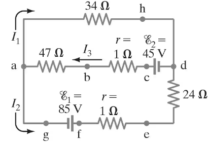
(II) (a) What is the potential difference between points a and d in Fig. 26–55 (similar to Fig. 26–12, Example 26–8), and (b) what is the terminal voltage of each battery?

Verified step by step guidance
1
Step 1: Analyze the circuit diagram provided in the problem. Identify the components such as resistors, batteries, and their arrangement (series or parallel). Note the values of resistances, battery emf (electromotive force), and internal resistances.
Step 2: To find the potential difference between points a and d, apply Kirchhoff's Voltage Law (KVL). Write the loop equation for the circuit, summing the voltage drops across resistors and batteries. Use the formula for voltage drop across a resistor: \( V = I \cdot R \), where \( I \) is the current and \( R \) is the resistance.
Step 3: Calculate the current in the circuit using Ohm's Law. For a single loop circuit, the total current \( I \) can be found using \( I = \frac{E_{total}}{R_{total}} \), where \( E_{total} \) is the sum of the battery emfs and \( R_{total} \) is the sum of all resistances (including internal resistances of the batteries).
Step 4: To determine the terminal voltage of each battery, use the formula \( V_{terminal} = E - I \cdot r \), where \( E \) is the emf of the battery, \( I \) is the current, and \( r \) is the internal resistance of the battery. Perform this calculation for each battery in the circuit.
Step 5: Substitute the calculated values of current and resistances into the equations derived in steps 2 and 4 to find the potential difference between points a and d, and the terminal voltage of each battery. Ensure all units are consistent (e.g., volts, ohms, amperes).

Verified video answer for a similar problem:

This video solution was recommended by our tutors as helpful for the problem above.
Video duration:
12m
Was this helpful?

Key Concepts

Here are the essential concepts you must grasp in order to answer the question correctly.

Potential Difference

Potential difference, or voltage, is the measure of electric potential energy per unit charge between two points in an electric field. It indicates how much work is needed to move a charge from one point to another. In circuits, it is crucial for determining how much energy is available to drive current through components.

Terminal Voltage

Terminal voltage is the voltage output of a battery when it is connected to a circuit. It can differ from the battery's electromotive force (EMF) due to internal resistance and the current flowing through the battery. Understanding terminal voltage is essential for analyzing how batteries perform under load.

Kirchhoff's Voltage Law

Kirchhoff's Voltage Law states that the sum of the electrical potential differences (voltage) around any closed circuit loop must equal zero. This principle is fundamental in circuit analysis, allowing us to calculate unknown voltages and currents by applying the law to various loops in the circuit.
Related Practice
Textbook Question

[In these Problems neglect the internal resistance of a battery unless the Problem refers to it.]


(II) A power supply has a fixed output voltage of 12.0 V, but you need VT = 3.0 V output for an experiment. (a) Using the voltage divider shown in Fig. 26–47, what should R₂ be if R₁ is 16.5 Ω? (b) What will the terminal voltage VT be if you connect a load to the 3.0-V output, assuming the load has a resistance of 7.0Ω?

141
views
Textbook Question

(III) (a) Determine the currents I1I2, and I3 in Fig. 26–58. Assume the internal resistance of each battery is r = 1.0 Ω.


(b) What is the terminal voltage of the 6.0-V battery?

845
views
Textbook Question

A voltage V is applied to n identical resistors connected in parallel. If the resistors are instead all connected in series with the applied voltage, show that the power transformed is decreased by a factor n².

1011
views
Textbook Question

(III) If the 25-Ω resistor in Fig. 26–59 is shorted out (resistance = 0 ), what then would be the current through the 15-Ω resistor?

857
views
Textbook Question

(II) Determine the magnitudes and directions of the currents in each resistor shown in Fig. 26–57. The batteries have emfs of ε1 = 9.0V and ε2 = 12.0V and the resistors have values of R1 = 25 Ω, R2 = 48 Ω, and R3 = 35 Ω.

(a) Ignore internal resistance of the batteries.

(b) Assume each battery has internal resistance r = 1.0 Ω.

911
views
Textbook Question

[In these Problems neglect the internal resistance of a battery unless the Problem refers to it.]


(III) You are designing a wire resistance heater to heat an enclosed container of gas. For the apparatus to function properly, this heater must transfer heat to the gas at a very constant rate. While in operation, the resistance of the heater will always be close to the value R = R₀, but may fluctuate slightly causing its resistance to vary a small amount ∆R ( << R₀ ). To maintain the heater at constant power, you design the circuit shown in Fig. 26–50, which includes two resistors, each of resistance R′. Determine the value for R′ so that the heater power P will remain constant even if its resistance R fluctuates by a small amount. [Hint: If ∆R << R₀ , then ΔPΔRdPdRR=R0\(\Delta\) P\(\approx\) \(\Delta\) R\(\left\). \(\frac{dP}{dR}\]\right\)|_{R=R_{0}}]

765
views