Ch. 28 - Sources of Magnetic Field
Giancoli Douglas - Physics for Scientists and Engineers 5th edition
Giancoli Douglas5th editionPhysics for Scientists and EngineersISBN: 9780137488179Not the one you use?Change textbook
Chapter 27, Problem 55

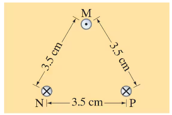
Three long parallel wires are 3.5 cm from one another. (Looking along them, they are at three corners of an equilateral triangle.) The current in each wire is 9.50 A, but its direction in wire M is opposite to that in wires N and P (Fig. 28–57). Determine the magnetic force per unit length on each wire due to the other two.


Verified step by step guidance
1
Step 1: Understand the problem setup. The three wires form an equilateral triangle with a side length of 3.5 cm. The current in wire M flows in the opposite direction to the currents in wires N and P. The goal is to calculate the magnetic force per unit length on each wire due to the other two wires. The magnetic force between two parallel currents is given by the formula: \( F/L = \frac{\mu_0 I_1 I_2}{2\pi d} \), where \( \mu_0 \) is the permeability of free space, \( I_1 \) and \( I_2 \) are the currents, and \( d \) is the distance between the wires.
Step 2: Calculate the magnetic force per unit length between any two wires. Since the triangle is equilateral, the distance \( d \) between any two wires is the same (3.5 cm = 0.035 m). Use the formula \( F/L = \frac{\mu_0 I_1 I_2}{2\pi d} \) to find the magnitude of the force per unit length between two wires. Substitute \( \mu_0 = 4\pi \times 10^{-7} \ \text{T·m/A} \), \( I_1 = I_2 = 9.50 \ \text{A} \), and \( d = 0.035 \ \text{m} \).
Step 3: Determine the direction of the forces. Use the right-hand rule to determine the direction of the magnetic force between each pair of wires. For wire M, the forces due to wires N and P will have components that need to be resolved into horizontal and vertical directions. Similarly, for wires N and P, consider the forces due to the other two wires and their directions.
Step 4: Resolve the forces into components. For wire M, the forces due to wires N and P will form an angle of 60° with each other (since the triangle is equilateral). Resolve these forces into horizontal and vertical components using trigonometric functions: \( F_x = F \cos(60°) \) and \( F_y = F \sin(60°) \). Add the components vectorially to find the net force per unit length on wire M. Repeat this process for wires N and P.
Step 5: Combine the results. After resolving the forces into components and summing them, calculate the net magnetic force per unit length on each wire. Ensure that the directions of the forces are consistent with the right-hand rule and the geometry of the setup. The final result will give the magnitude and direction of the force per unit length on each wire.

Verified video answer for a similar problem:

This video solution was recommended by our tutors as helpful for the problem above.
Video duration:
6m
Was this helpful?

Key Concepts

Here are the essential concepts you must grasp in order to answer the question correctly.

Magnetic Field Due to a Current-Carrying Wire

A long straight wire carrying an electric current generates a magnetic field around it. The direction of the magnetic field can be determined using the right-hand rule, where the thumb points in the direction of the current and the curled fingers indicate the direction of the magnetic field lines. The strength of the magnetic field at a distance 'r' from the wire is given by the formula B = (μ₀I)/(2πr), where μ₀ is the permeability of free space and I is the current.

Magnetic Force Between Parallel Wires

When two parallel wires carry currents, they exert magnetic forces on each other. The force per unit length between two parallel wires is given by the formula F/L = (μ₀I₁I₂)/(2πd), where I₁ and I₂ are the currents in the wires, d is the distance between them, and μ₀ is the permeability of free space. The direction of the force is attractive if the currents are in the same direction and repulsive if they are in opposite directions.

Superposition Principle in Magnetism

The superposition principle states that the total magnetic force acting on a wire due to multiple other wires is the vector sum of the individual forces exerted by each wire. In this scenario, each wire experiences forces from the other two wires, and these forces must be calculated separately and then combined, taking into account their directions and magnitudes to find the net force per unit length on each wire.
Related Practice
Textbook Question

(III) Use the result of Problem 44 to find the magnetic field at point P in Fig. 28–53 due to the current in the square loop.


583
views

Textbook Question

Helmholtz coils are two identical circular coils having the same radius 𝑅 and the same number of turns N, separated by a distance equal to the radius 𝑅 and carrying the same dc current I in the same direction. (See Fig. 28–61.) They are used in scientific instruments to generate nearly uniform magnetic fields. (They can be seen in the photo, Fig. 27–19.) (a) Determine the magnetic field B at points 𝓍 along the line joining their centers. Let 𝓍 = 0 at the center of one coil, and 𝓍 = 𝑅 at the center of the other. (b) Show that the field midway between the coils is particularly uniform by showing that dB/d𝓍 = 0 and d²B/d𝓍² = 0 at the midpoint between the coils. (c) If 𝑅 = 10.0 cm, N = 85 turns and I = 3.0 A, what is the field at the midpoint between the coils, 𝓍 = 𝑅/2?

849
views
Textbook Question

A long horizontal wire carries a current of 42 A. A second wire, made of 1.00-mm-diameter copper wire and parallel to the first, is kept in suspension magnetically 5.0 cm below (Fig. 28–60). (a) Determine the magnitude and direction of the current in the lower wire. (b) Is the lower wire in stable equilibrium? (c) Repeat parts (a) and (b) if the second wire is suspended 5.0 cm above the first due to the first’s magnetic field.

620
views
Textbook Question

In Fig. 28–57 the top wire is 1.00-mm-diameter copper wire and is suspended in air due to the two magnetic forces from the bottom two wires. The current is 35.0 A in each of the two bottom wires. Calculate the required current in the suspended wire (M).

1179
views
Textbook Question

(III) A square loop of wire, of side d, carries a current I. (a) Determine the magnetic field B at points on a line (call it the 𝓍 axis) perpendicular to the plane of the square which passes through the center of the square (Fig. 28–56). Express B as a function of 𝓍, the distance from the center of the square. (b) For 𝓍 ≫ d, does the square appear to be a magnetic dipole? If so, what is its dipole moment?


812
views
Textbook Question

(II) Consider a straight section of wire of length d, as in Fig. 28–51, which carries a current I. (a) Show that the magnetic field at a point P a distance 𝑅 from the wire along its perpendicular bisector is


B=μ0I2πRd(d2+4R2)12B = \(\frac{\mu_0 I}{2\pi R}\) \(\frac{d}{(d^2 + 4R^2)^{\frac{1}{2}\)}}


(b) Show that this is consistent with Example 28–10 for an infinite wire.

646
views