
Ch. 30 - Inductance, Electromagnetic Oscillations, and AC Circuits
Giancoli Douglas - Physics for Scientists and Engineers 5th edition
Giancoli Douglas5th editionPhysics for Scientists and EngineersISBN: 9780137488179Not the one you use?Change textbook
Chapter 29, Problem 27

Two tightly wound solenoids have the same length and circular cross-sectional area. But solenoid 1 uses wire that is 1.5 times as thick as solenoid 2.
(a) What is the ratio of their inductances?
(b) What is the ratio of their inductive time constants? (Assume the only resistance in the circuits is that of the wire itself.)

Verified step by step guidance
1
The inductance of a solenoid is given by the formula: L = μ2n2π .

Verified video answer for a similar problem:

This video solution was recommended by our tutors as helpful for the problem above.
Video duration:
3m
Was this helpful?

Key Concepts

Here are the essential concepts you must grasp in order to answer the question correctly.

Inductance

Inductance is a property of an electrical circuit that quantifies the ability of a solenoid or coil to store energy in a magnetic field when an electric current flows through it. It is influenced by factors such as the number of turns in the coil, the cross-sectional area, and the material's permeability. The inductance (L) of a solenoid can be calculated using the formula L = (μ₀ * N² * A) / l, where μ₀ is the permeability of free space, N is the number of turns, A is the cross-sectional area, and l is the length of the solenoid.
Recommended video:
Guided course
12:59
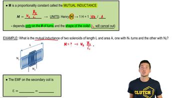
Mutual Induction

Resistance and Wire Thickness

The resistance of a wire is determined by its resistivity, length, and cross-sectional area, following the formula R = ρ * (l / A). When comparing two solenoids with different wire thicknesses, the thicker wire (solenoid 1) will have a lower resistance due to its larger cross-sectional area. This difference in resistance affects the inductive time constant, which is the time it takes for the current to reach approximately 63% of its maximum value in an RL circuit.
Recommended video:
Guided course
09:57
Magnetic Force on Current-Carrying Wire

Inductive Time Constant

The inductive time constant (τ) is a measure of how quickly the current in an inductor reaches its steady state when a voltage is applied. It is defined as τ = L / R, where L is the inductance and R is the resistance of the circuit. A larger inductance or a smaller resistance results in a longer time constant, indicating that the current will take more time to stabilize. In the context of the two solenoids, the ratio of their time constants will depend on the ratio of their inductances and resistances.
Recommended video:
Guided course
08:59
Phase Constant of a Wave Function
Related Practice
Textbook Question

Two tightly wound solenoids have the same length and circular cross-sectional area. But solenoid 1 uses wire that is 1.5 times as thick as solenoid 2. What is the ratio of their inductive time constants? (Assume the only resistance in the circuits is that of the wire itself.)

97
views
Textbook Question

(III) Determine the emf induced in the square loop in Fig. 29–52 if the loop stays at rest and the current in the straight wire is given by I(t) = (15.0 A) sin (2200 t) where t is in seconds. The distance a is 12.0 cm, and b is 15.0 cm.

175
views
Textbook Question

(II) A 25-mH coil whose resistance is 0.80 Ω is connected to a capacitor C and a 420-Hz source voltage. If the current and voltage are to be in phase, what value must C have?

1258
views
Textbook Question

(II) Suppose that the U-shaped conductor and connecting rod in Fig. 29–12a are oriented vertically (but still in contact) so that the rod is falling due to the gravitational force. Find the terminal speed of the rod if it has mass m = 3.6 grams, length 𝓁 = 18 cm, and resistance R = 0.0013 Ω. It is falling in a uniform horizontal field B = 0.080 T. Neglect the resistance of the U-shaped conductor, and friction.

1460
views
Textbook Question

(II) (a) Determine the energy stored in the inductor L as a function of time for the LR circuit of Fig. 30–6a. (b) After how many time constants does the stored energy reach 99.9% of its maximum value?

1542
views
Textbook Question

(II) (a) In Fig. 30–28, assume that the switch has been in position A for sufficient time so that a steady current I₀ = V₀/R flows through the resistor R. At time t = 0, the switch is quickly switched to position B and the current decays through resistor R' (which is much greater than R) according to I=I0et/τI = I_0 e^{-t/\(\tau\)'}I=I0et/τI = I_0 e^{-t/\(\tau\)'}. Show that the maximum emf εmax induced in the inductor during this time period is (R'/R)Vo. (b) If R' = 45R and Vo = 145 V, determine εmax. [When a mechanical switch is opened, a high-resistance air gap is created, which is modeled as R' here. This Problem illustrates why high-voltage sparking can occur if a current-carrying inductor is suddenly cut off from its power source. The very high voltage can produce an electric field great enough to ionize atoms of air, which emit light when electrons recombine with the ions.]

1378
views