
Ch. 28 - Sources of Magnetic Field
Giancoli Douglas - Physics for Scientists and Engineers 5th edition
Giancoli Douglas5th editionPhysics for Scientists and EngineersISBN: 9780137488179Not the one you use?Change textbook
Chapter 27, Problem 18

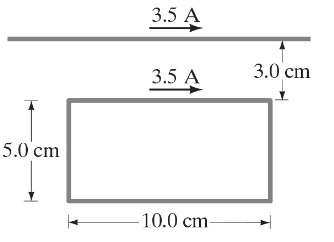
"(II) A rectangular loop of wire is placed next to a straight wire, as shown in Fig. 28–40. There is a dc current of 3.5 A in both wires. Determine the magnitude and direction of the net force on the loop.


Verified step by step guidance
1
Step 1: Understand the problem setup. The rectangular loop of wire is placed next to a straight wire, and both carry a DC current of 3.5 A. The goal is to calculate the net force on the loop due to the magnetic interaction between the two wires. The magnetic force arises because the current in the straight wire generates a magnetic field, which interacts with the current in the loop.
Step 2: Recall the formula for the magnetic field generated by a straight wire. The magnetic field at a distance \( r \) from a long straight wire carrying current \( I \) is given by \( B = \frac{\mu_0 I}{2 \pi r} \), where \( \mu_0 \) is the permeability of free space (\( \mu_0 = 4 \pi \times 10^{-7} \; \text{T·m/A} \)). Use this formula to calculate the magnetic field at the location of each segment of the loop.
Step 3: Analyze the forces on each segment of the loop. The loop has four sides: two parallel to the straight wire and two perpendicular. For the parallel sides, the magnetic field from the straight wire interacts with the current in the loop, producing forces. Use the formula for the magnetic force on a current-carrying wire: \( F = I L B \), where \( I \) is the current, \( L \) is the length of the wire segment, and \( B \) is the magnetic field. Determine the direction of the forces using the right-hand rule.
Step 4: Consider the forces on the perpendicular sides of the loop. The magnetic field from the straight wire is parallel to these sides, so the force on these segments will be zero because the angle between the current direction and the magnetic field is 0° (\( F = I L B \sin \theta \), and \( \sin 0° = 0 \)).
Step 5: Calculate the net force on the loop. Add the forces from the two parallel sides, taking into account their magnitudes and directions. The forces may partially or completely cancel depending on the relative positions of the loop and the straight wire. Use vector addition to determine the net force and its direction.

Verified video answer for a similar problem:

This video solution was recommended by our tutors as helpful for the problem above.
Video duration:
13m
Was this helpful?

Key Concepts

Here are the essential concepts you must grasp in order to answer the question correctly.

Magnetic Field Due to a Current-Carrying Wire

A straight wire carrying an electric current generates a magnetic field around it, described by the right-hand rule. The direction of the magnetic field lines forms concentric circles around the wire, with the strength of the field decreasing with distance from the wire. This magnetic field interacts with other currents, such as those in nearby loops, influencing their motion.
Recommended video:
Guided course
09:57
Magnetic Force on Current-Carrying Wire

Lorentz Force

The Lorentz force is the force experienced by a charged particle moving through a magnetic field. For a current-carrying conductor, this force can be calculated using the formula F = I(L × B), where I is the current, L is the length vector of the conductor, and B is the magnetic field. The direction of the force is determined by the right-hand rule, which helps predict how the loop will move in response to the magnetic field created by the straight wire.
Recommended video:
Guided course
13:39
Lorentz Transformations of Velocity

Superposition of Forces

In physics, the principle of superposition states that when multiple forces act on an object, the total force is the vector sum of all individual forces. In the context of the rectangular loop near the straight wire, the net force on the loop is determined by considering the magnetic forces acting on each segment of the loop due to the magnetic field from the straight wire. This requires analyzing the contributions from each segment to find the overall effect on the loop.
Recommended video:
Guided course
03:32
Superposition of Sinusoidal Wave Functions
Related Practice
Textbook Question

(II) Two long parallel wires 8.20 cm apart carry 19.5-A dc currents in the same direction. Determine the magnetic field vector at a point P, 12.0 cm from one wire and 13.0 cm from the other. See Fig. 28–43. [Hint: Use the law of cosines. See Appendix A or inside rear cover.]

591
views
Textbook Question

(II) Two long straight wires each carry a dc current I out of the page toward the viewer, Fig. 28–38. Indicate, with appropriate arrows, the direction of B\(\overrightarrow{B}\) at each of the points 1 to 6 in the plane of the page. State if the field is zero at any of the points.

720
views
Textbook Question

(II) Two long thin parallel wires 13.0 cm apart carry 25-A currents in the same direction. Determine the magnetic field vector at a point 10.0 cm from one wire and 6.0 cm from the other (Fig. 28–37). [Hint: You could try using the law of cosines, Appendix A.]

550
views
Textbook Question

(II) Two long wires are oriented so that they are perpendicular to each other. At their closest, they are 20.0 cm apart (Fig. 28–42). What is the magnitude of the magnetic field at a point midway between them if the top one carries a current of 18.0 A and the bottom one carries 12.0 A?

510
views
Textbook Question

(II) In Fig. 28–36, a long straight wire carries current I out of the page toward you. Indicate, with appropriate arrows, the direction and (relative) magnitude of B\(\overrightarrow{B}\) at each of the points C, D, and E in the plane of the page.

752
views
Textbook Question

(II) Let two long parallel wires, a distance d apart, carry equal dc currents I in the same direction. One wire is at 𝓍 = 0, the other at 𝓍 = d, Fig. 28–41. Determine B\(\overrightarrow{B}\) along the 𝓍 axis between the wires as a function of 𝓍.

830
views