
Ch. 28 - Sources of Magnetic Field
Giancoli Douglas - Physics for Scientists and Engineers 5th edition
Giancoli Douglas5th editionPhysics for Scientists and EngineersISBN: 9780137488179Not the one you use?Change textbook
Chapter 27, Problem 62

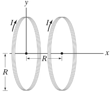
Helmholtz coils are two identical circular coils having the same radius 𝑅 and the same number of turns N, separated by a distance equal to the radius 𝑅 and carrying the same dc current I in the same direction. (See Fig. 28–61.) They are used in scientific instruments to generate nearly uniform magnetic fields. (They can be seen in the photo, Fig. 27–19.) (a) Determine the magnetic field B at points 𝓍 along the line joining their centers. Let 𝓍 = 0 at the center of one coil, and 𝓍 = 𝑅 at the center of the other. (b) Show that the field midway between the coils is particularly uniform by showing that dB/d𝓍 = 0 and dΒ²B/d𝓍² = 0 at the midpoint between the coils. (c) If 𝑅 = 10.0 cm, N = 85 turns and I = 3.0 A, what is the field at the midpoint between the coils, 𝓍 = 𝑅/2?

Verified step by step guidance
1
Step 1: Begin by understanding the setup of Helmholtz coils. These are two identical circular coils separated by a distance equal to their radius R, carrying the same current I in the same direction. The goal is to calculate the magnetic field B along the axis joining their centers, and analyze its uniformity at the midpoint.
Step 2: Use the Biot-Savart law to derive the magnetic field produced by a single coil at a point along its axis. The magnetic field at a distance x from the center of a single coil is given by: B=ΞΌβ‚€NIRΒ²2(RΒ²+xΒ²)3/2. Here, ΞΌβ‚€ is the permeability of free space, N is the number of turns, I is the current, R is the radius, and x is the distance from the coil center.
Step 3: For Helmholtz coils, the total magnetic field at a point x along the axis is the sum of the fields produced by both coils. Let the first coil be centered at x = 0 and the second coil at x = R. The total field is: B=B₁(x)+Bβ‚‚(x), where B₁(x) and Bβ‚‚(x) are the fields from the first and second coils respectively.
Step 4: To analyze the uniformity of the field at the midpoint (x = R/2), calculate the first derivative dB/dx and the second derivative dΒ²B/dxΒ² of the total field B with respect to x. Show that both derivatives are zero at x = R/2, indicating that the field is particularly uniform at this point.
Step 5: Finally, substitute the given values (R = 10.0 cm, N = 85 turns, I = 3.0 A) into the formula for B at x = R/2 to calculate the magnetic field at the midpoint. Use the derived expression for B and ensure all units are consistent (e.g., convert cm to meters for calculations).

Verified video answer for a similar problem:

This video solution was recommended by our tutors as helpful for the problem above.
Video duration:
7m
Was this helpful?

Key Concepts

Here are the essential concepts you must grasp in order to answer the question correctly.

Magnetic Field of a Coil

The magnetic field generated by a circular coil of wire is determined by the current flowing through it and the number of turns in the coil. The magnetic field at the center of a single loop is given by the formula B = (ΞΌβ‚€ * I) / (2 * R), where ΞΌβ‚€ is the permeability of free space, I is the current, and R is the radius of the coil. For Helmholtz coils, the configuration allows for the superposition of the magnetic fields from both coils, leading to a more uniform field in the region between them.

Superposition Principle

The superposition principle states that when two or more magnetic fields overlap, the resultant field at any point is the vector sum of the individual fields. In the case of Helmholtz coils, the magnetic fields produced by each coil at a point along the axis can be added together to find the total magnetic field. This principle is crucial for analyzing the field strength and uniformity between the coils.

Uniform Magnetic Field

A uniform magnetic field is one where the magnetic field strength is constant in magnitude and direction throughout a specified region. For Helmholtz coils, the design aims to create a uniform field between the coils, particularly at the midpoint. This uniformity can be mathematically verified by showing that the first derivative of the magnetic field with respect to position is zero (dB/dx = 0) and that the second derivative is also zero (dΒ²B/dxΒ² = 0) at that point, indicating no change in field strength.
Related Practice
Textbook Question

The power cable for an electric trolley (Fig. 27–60) carries a horizontal current of 330 A toward the east. The Earth’s magnetic field has a strength 5.0 x 10⁻⁵ T and makes an angle of dip of 22Β° at this location. Calculate the magnitude and direction of the magnetic force on a 15-m length of this cable.


1491
views
Textbook Question

A long horizontal wire carries a current of 42 A. A second wire, made of 1.00-mm-diameter copper wire and parallel to the first, is kept in suspension magnetically 5.0 cm below (Fig. 28–60). (a) Determine the magnitude and direction of the current in the lower wire. (b) Is the lower wire in stable equilibrium? (c) Repeat parts (a) and (b) if the second wire is suspended 5.0 cm above the first due to the first’s magnetic field.

620
views
Textbook Question

You want to get an idea of the magnitude of magnetic fields produced by overhead power lines. You estimate that a transmission wire is about 12 m above the ground. The local power company tells you that the lines operate at 145 kV and provide a maximum of 45 MW to the local area. Estimate the maximum magnetic field you might experience walking under one such power line, and compare to the Earth’s field. [For an ac current, values are rms, and the magnetic field will be changing.]

733
views
Textbook Question

In Fig. 28–57 the top wire is 1.00-mm-diameter copper wire and is suspended in air due to the two magnetic forces from the bottom two wires. The current is 35.0 A in each of the two bottom wires. Calculate the required current in the suspended wire (M).

1179
views
Textbook Question

Three long parallel wires are 3.5 cm from one another. (Looking along them, they are at three corners of an equilateral triangle.) The current in each wire is 9.50 A, but its direction in wire M is opposite to that in wires N and P (Fig. 28–57). Determine the magnetic force per unit length on each wire due to the other two.


740
views
Textbook Question

A set of Helmholtz coils (see Problem 62, Fig. 28–61) have a radius 𝑅 = 10.0 cm and are separated by a distance 𝑅 = 10.0 cm . Each coil has 85 loops carrying a current I = 2.0 A. Graph B as a function of 𝓍.

640
views